
This post is a continuation of a post from back in 2012. In that earlier post I mentioned my desire to replace the 110v gear reduction motor on my Hitachi CB75F, which screams like a banshee, with the 3-phase Hitachi version, which was not made available in the US for some reason. Unfortunately, my plans were thwarted because Hitachi refused to sell the 3-phase motor if it was to be exported from Japan.
And I know I could have thrown on a different, non-Hitachi motor, as several folks have done over the years, but those conversions, to my eyes, were not all that appealing. I wanted the clean seamlessness of a factory install, with equipment designed to fit, with belt guarding retained, and so forth. So, back in 2012 I did nothing and just put up with ‘the screamer’ for the years to follow.
Now that I’m reconfiguring my shop in the basement, the issue of machinery noise has become again a factor to examine, and I started thinking once more about converting the CB75 to a 3-phase motor. The same problem remained though, with Hitachi being unwilling to sell the motor, and besides, the Japanese domestic 3-phase is 200v., which is okay on typical 208v. 3-phase service, but was not likely to be so happy, in my estimation, with the 240v. feed that my Phase Perfect outputs. I started to consider if it might be better to sell the saw and get something else. Trouble is, the ‘good’ bandsaws are nearly all too tall for my basement.
By some odd sort of coincidence, one day I was looking around on Ebay and stumbled onto a listing for a 3-phase motor that came from a Hitachi B-600a bandsaw, the predecessor of the CB-75F. I think these were made until around 1992. The seller had removed the motor and converted their machine to a single phase motor to suit their situation. I had not known that the B-600a had been available in the US in a 3-phase version, nor do I know why they stopped offering it, though I have my suspicions. But I was quite confident that the motor used on the B-600a was going to be the same thing that would have been fitted to 3-phase versions of the CB-75F. And the nice thing was that the US-market motor was of 220v. x 60Hz. spec, which would mean it would work with my Phase Perfect and its 240v. output.
I made the seller an offer of $75.00, which was accepted. The motor arrived, and sure enough, it bolted right into place on the mounting plate, and the drive pulley off of the single phase unit bolted right on as well. I then contacted my supplier in Japan and, based on a careful comb-through of the machine’s parts diagram, ordered all of the components which were spec’d as for 3-phase use, including electrical cord, drive belts, belt guard, 3-phase push-button switch and switch box. That lot cost me less than $200.00.
One day I set to work installing the components, and after un-packaging the switch noticed something unexpected. My past experience with 3-phase switches was that they had six terminals, 3 for the input side, and 3 for the output. But this switch had only 4 connection points:

This was mystifying. I grew angry and smashed it with a hammer – – just kidding.
I scratched my head for a good long while trying to think of some way in which the motor could be turned on and off using a switch with just 4 terminals. I checked the function of the switch using a multimeter, and sure enough, the switch was clearly designed to turn on and off 2 leads only. Then I wondered if somehow you were meant to solder on connections to the two middle rivets. That seemed implausible, and a check with the multimeter confirmed they were not a part of the switching.
Here’s a look at the front of the switch:

It’s a simple manual non-momentary push button switch. When the green button is depressed, the red one pops up and vice-versa. It’s a cute l’il thing!
Naturally, I searched the internet to see if I could find some reference to controlling a 3-phase motor by switching on and off 2 of the 3 leads. Was there some sort of non-intuitive wiring arrangement in which this could work? I found nothing. The only thing that associated to the condition was a situation in which the motor was powered though the switch, and then one of the leads lost power, aka ‘single phasing’. I’ve had this happen to me a couple of times actually. In both cases, the circuit breaker failed on one of the three lines.
When a motor is powered and then loses a phase, it will keep operating – at least mine did, but the motor can be damaged through overheating, more so, from what I understand, if the 3-phase wiring is arranged in ‘Delta’ format. When you try to restart the motor with a phase down you will find the motor will not power up. You just get some weird noises from the motor that don’t sound too good. Like it is trying to start turning but cannot. At first this situation looks very much like the problem resides with the motor. In reality, the first place to check however is the circuit breaker in the load center. In the case of 208v. 3-phase delivery, each of the three terminals of the circuit breaker should show 120v. to ground when checked with a multimeter.
A 3-phase motor, which is actually the simplest sort of AC motor, has the leads arranged around the motor in a equilateral triangle arrangement, spaced 120˚ apart. AC induction motors (also known as asynchronous motors) use a rotating magnetic field to produce torque. When all three leads of the motor receive power, an electric field forms and the motor commences turning. When only 2 of the 3 leads are powered however, the electric field does not form as normal and the motor is unable to start spinning.
Similarly, in a split phase 240v. motor (like you have domestically in the mains power that comes into the house load center and goes out to, say, an electric clothes dryer motor or water heater, with two 120v. leads and a ground), when power is applied to both leads, an electric field forms. A split-phase motor is simply a single-phase motor which utilizes an internal, often centrifugal switch in conjunction with a starting capacitor, to momentarily energize a different tap on the motor winding with a voltage of a different phase angle relative to the input voltage, in order to provide the necessary starting torque to the driven load as the motor comes up to speed.
In a single phase 120v. motor the situation is a slightly different. A motor’s coils driven by a single AC phase all alternate at the same time, reversing north and south poles in unison. This creates a problem called ‘zero starting torque’. While it can run a motor already spinning, it has no “kick” to get a motor to turn from a dead stop. There are a number of solutions to this, and they involve what are called ‘starting capacitors’. A capacitor, connected to a separate coil on the motor, creates an alternating electric current ahead of the main phase by 90 degrees. This happens, as I understand it, because the current through a capacitor leads the voltage by 90 degrees. During a motor’s start-up, a switch connects a capacitor and a special starting coil to the motor. After the motor reaches its operating speed, the switch disconnects the capacitor. If the capacitor remains connected to the motor, it puts a drag on the motor’s efficiency.
However, with all of the above general info, I could find no commentary anywhere about what happens to a 3-phase motor when only 1 lead has power. Logically though, an electric field cannot be formed in such a situation and the motor cannot spin and should therefore consume no current. But might having a single lead with power damage the motor somehow? That I wasn’t sure about, but again, no field established equals no current draw it seems to me.
I decided to pose the question of controlling a 3-phase motor using a switch on 2 leads on a section of the Practical Machinist forum. I did not however receive much in the way of useful information, though several fellows shared their opinions.
The thing with electricity is that at a certain level it is readily understandable. People can make calculations using, say, ohm’s law, and people have experiences connecting electrical parts together according to well-established systems. But at a deeper level, I think actually very few people truly understand electricity. I’m hardly an original in concluding this. See this link for more, and be prepared for a lengthy read. There was a genius named Nicola Tesla, and he seemed to have an understanding that was on another level from the rest of us. Same could be said of Faraday, Coulomb, and Ampere. And just because an electrical engineer or mathematician can make calculations does not mean they have near that level of understanding. Let’s face it our school system plays a large role in completely befuddling the populace in that subject area.
I think my question about whether starting a 3-phase motor switching only 2 leads is in the category of requiring a deeper understanding of how exactly a 3-phase motor works. And it seems there are very few people out there with that level of understanding. Certainly none on the PM forum (willing to share) it would appear.
Initial answers were along the typical male communication lines of skepticism and “well, I’ve never seen that before so it must be wrong”. Many guys come at you from the get-go presumption that you are some species of idiot – the PM forum has no shortage of these folks. And, to be fair, there are some incredibly helpful people there too. Sometimes you have to wade through a swamp to find them, that’s all.
Several folks insisted that some parts must be missing and that the switch had to be used in tandem with a contactor or mag switch- this, even though I had explained I had ordered every 3-phase specific part listed by Hitachi. My dealer in Japan also thoroughly checked. Just to be sure, I checked the parts listing again and sure enough, nothing electrically related was listed there, or shown in the parts diagram, besides the motor, the cable and the switch, that had been missed.
One little note I can add is that if you have a Japanese power tool of some sort and need parts, it is often the case that when you look on US-based sites (like ereplacementparts.com for instance), you will find that most of the parts listed are marked ‘obsolete’, ‘no longer available’ and so forth. In some cases about all they list for some machines is standard metric nuts and bolts. It’s when you look in Japan that you discover that most of the parts are often still available there. And they are in brand new packaging with current part numbers, not like we’re talking dusty NOS items scavenged from some sort of dark crypt. They don’t bother sending the stuff overseas for some reason.
Okay, back to my quest. Next of course came the suggestions to take that factory part off and put a conventional American 6 terminal 3-phase switch. I wanted to avoid putting a typical clunky and oversized NA-spec switch on the machine. The factory switch was attractive and designed for the machine. Does anyone seriously think that a huge entity like Hitachi would design a machine with dangerous or sub-standard switch gear?
I still was left though with little more than a theory that the motor was controlled by switching 2 leads on or off – it was the only explanation which fit the facts presented by the parts sitting in front of me.
I contacted Mark Hennebury from Solid Wood Machinery in Ontario and explained the situation. He said he had never seen something like that before, and was not sure of whether it was an acceptable thing to do or not. He also admitted not being formally trained in the area of machine electrical wiring. He also pointed out the safety advantages of using a magnetic switch as compared to a manual push button switch, however that was something of which I am well aware. We conversed some more, over email and phone, and he admitted he did not have the answer.
I always respect people, like Mark, who are very knowledgable in their field and yet will state clearly what the limits of their knowledge are. It’s a mark of intelligence and humility.
The opposite are folks -and they are legion unfortunately – who lack knowledge and competence but estimate that they are knowledgable and competent:
“In 2011, David Dunning wrote about his observations that people with substantial, measurable deficits in their knowledge or expertise lack the ability to recognize those deficits and, therefore, despite potentially making error after error, tend to think they are performing competently when they are not: “In short, those who are incompetent, for lack of a better term, should have little insight into their incompetence—an assertion that has come to be known as the Dunning–Kruger effect“
With a lot of technical stuff, you tend to come across a lot of guys – generally it is guys as they have been socialized in this culture to seek status through displays of knowledge and competence – who make all sorts of assertions about things based on very little actual knowledge. There is a reason the term ‘mansplaining’ has entered the lexicon, and the reasons are clear enough. And what tends to go with that is an extreme reluctance among some to acknowledge when they are wrong. Usually, they just go silent if it is pointed out they do not have s good understanding. The places to see this on display with high frequency are internet forums. I have noticed that most forums on subjects of a technical nature are overwhelming populated by men.
Anyway, leaving that aside, with some help with a friend, I learned of a fellow working in Japan who was in a shop that had a B-600a bandsaw. That fellow offered to open up the motor connection cover and switch and take some photos of the wiring connections. That was amazing! People can be incredibly generous sometimes.
A few days later I received the photos. The first one showed the wiring connection at the motor’s junction box:

I could see the motor side wiring on the lower portion of the photo was identical to my motor. The supply side wiring employed the same cable, with the same 4 wire colors, namely red, black, white, and green. The exact situation of which wire connected to what however was a little unclear from the picture, but it seemed that the red wire from the supply side connected to the terminal block directly. The white and black wires were spliced with crimped terminals to the exiting cable, and a green wire connected to the ground lug just visible to the right. Another green wire connects to the supply side middle terminal. This oddity is the first clue as to what is going on.
What was different about the B-600a wiring as compared to the CB-75F was the basic arrangement of how the electrical cable is arranged on the machine. On the B-600a, the supply cable comes into the motor junction box first, then another identical 4-wire cable comes out from the motor and goes up to the on/off switch, where it terminates. On the CB-75F, the machine cable runs first to the switch, then out of the switch and terminates at the motor. Despite this difference of arrangement, the electrical components involved were the same between the two machines as far as I could tell. I figured I could make sense of it despite the difference of arrangement.
Here’s the switch on the B-600a:

The escutcheon is the same as on my machine, just mounted directly on the front of the upper blade housing whereas on my saw it fits into a metal box along the machine’s column.
The fellow in Japan went as far as he could without taking things completely apart. One picture from the back of the switch proved to be the key to the puzzle for me:

Why was this picture the key to the puzzle? It relates to wire colors. The machine cord has 4 colors of wire in it, and of those 4 wires one had to serve as the ground and the other three were going to be the leads. The picture of the motor junction box showed previously that green is the ground, and of course by convention I would normally make green the ground wire anyhow. But in the picture above you can see that one of the leads soldered to the switch is the green. Does that mean that the ground is being switched on and off? No. It means that, for the machine cord coming up from the motor, the use of the 4 colors is different than for the cable coming into the motor as the supply. In other words, at the switch, with its 4 terminals, are connected 4 wires, two to one side of the switch, and two to the other side. The colors don’t matter at all, and the fact that they are using the same exact cord with the same 4 wire colors from the motor up to the switch means only that they are economizing rather than having a separate cord with, say, two black and two white wires or something like that. At the switch, in other words, the green wire is not a ground, but it is simply being ‘nominated’ or substituted for a more conventional color used for a lead.
So, it seemed to me that the supply cable comes into the motor junction box, and the green wire connects to the ground lug. The red wire connects to the terminal block. The black and the white wires are spliced to the other cord heading up to the switch. At the switch, the black and the white are soldered onto one side’s pair of terminals, while the remaining two wires in that cable, namely the red and the green, connect to the other side of the switch. Back down at the motor junction box, the red and the green, which are actually continuations of the black and white, connect to the terminal block.
I felt sure of my conclusion, sufficient to the point that I went and soldered the wire connections to the switch on my machine. That was a big challenge for me due to my neuropathy, and I felt triumphant just to be able to complete the task cleanly, and without damaging anything. I put the switch into its housing, complete with insulator piece, and buttoned the rest up.
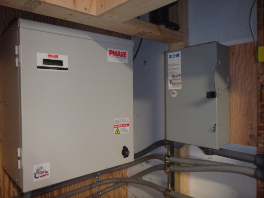
That situation remained unchanged until today. I had previously wired up my Phase Perfect and had established a line out from the phase converter to a small load center, and then ran a line along the wall and down to a receptacle.
I was talking to a friend about the install, and he suggested I double check the wire gauge as his own phase converter, though a different model and type of converter, had required a #6 AWG feed from the main panel. I had thought I had used #6 AWG for that, but upon closer inspection with glasses on, I discovered I should have looked with glasses on in the first place as what I took to be a ‘6’ was in fact an ‘8’. The wire was thereby slightly undersized. Doh! So I ripped it out. Researching, I also discovered that #6 was only going to work if it was of the 90˚C variety. Other types of #6 (the 60˚C and 75˚C types) are not rated as highly for amperage capacity.
I also decided, upon further reflection, to put a disconnect switch in between the house load center and the Phase Perfect. While it appeared to be legal in the electrical code to use a circuit breaker to turn a device on and off, and lots of people do just that, when you dig into the matter a little further it became apparent that a circuit breaker, while it can function as an on/off switch, is not in fact designed as a switch, and there are scenarios in which wear and tear from frequent switching can lead to conditions where the circuit breaker would not perform properly under a short circuit condition. It seemed prudent to use a device which was designed from the get-go as a switch and not a circuit protection device. I know this might be heretical to some, but I can live with that.
Anyway, December was a bit of a disaster zone for getting things done around here as I had my painful knee issue and the family was struck by a nasty endless cold that lingered 3 weeks. Also, my wife’s car died (cylinder head gasket and rad) and was scrapped, and we were down to one car, which meant my wife used my car to get to work and I was housebound. My knee situation, combined with snow and ice on the ground meant I was unwilling to venture out.
Have you ever been housebound and physically not your best for 5 weeks straight? That was the end of the year situation for me. I started to get depressed and stir crazy. I’m an active person who likes to do stuff, and sitting on the couch for weeks was not for me.
Anyhow, a neighbor who is a folk musician in on tour for three months and he has lent me his old Toyota Tacoma to drive. So, a couple of days ago I was able to get out of the house and over to the local electrical supply and pick up some #6 AWG to complete my Phase Perfect install. Here’s how that looks:
I’m going to run though next what happens with the Phase Perfect when you flip the disconnect switch to the ‘on’ position. I think it is kinda neat.
First off the small screen lights up and you get the following message:

A few seconds later the first of the checking routines commence…

Here’s the input voltage (nominally 240v. split phase):

A few seconds after that:

Next:

This tells you that no current is being used, which is what you would expect as no machines on the lone installed circuit were on.
Finally, a most reassuring message (especially the first time I fired it up):

Takes around 30 seconds for the PP to go through those steps.
So now over to the bandsaw. This is the completed install, which is completely factory correct, save for a difference in the motor paint color from the rest of the machine:

I pushed the button, and my shop exploded like a bomb went…. nah! It fires up just fine, and funs oh so quietly. ahhhh! This my friends is the only factory 3-phase CB-75F in the country as far as I know. Yah, I know, big deal. I do need to get out more.
Back at the Phase Perfect, with the bandsaw motor running, we see some new information:

That’s about what I would expect as far as amperage draw for an unloaded 2 hp. 3-phase bandsaw motor.
I like how the Phase Perfect has the diagnostic functionality. I’m pleased that after buying it secondhand, though slightly used, it works perfectly. And when it is operating it is super quiet. A held a phone up to it the other day while talking to a friend and he couldn’t hear it at all.
And I feel vindicated too that my analysis of the motor and switch connections proved to be correct despite the naysayers and doomsday predictors. Big thanks to the guy in Japan who provided those photos to me of his B-600a.
Of course, once I posted up on Practical Machinist forum that the switching of 2-phases to control a 3-phase motor in fact did work, immediately someone posted up warning me of dire safety consequences and that the switch would fail “soon”. When I replied by asking him to describe succinctly what the safety issues were and what the failure mode was going to be, and how long I might have until motor or switch failure became evident, nothing but silence was heard in return. It’s as if I were one of those first Europeans to try and sail across the Atlantic and had to listen to dire warnings about falling off the edge of the (flat) world.
I would love to talk to someone who actually knows their stuff to explain to me why Hitachi would choose to operate a 3-phase motor by switching 2 leads and not 3, and what advantages and disadvantages might associate to that design, but I’m not holding my breath. Like I said, few people truly understand electricity – myself included! I kinda suspect the design allows for a smaller switch than otherwise.
All for now. Hope you enjoyed the read.
I don’t understand electricity either, but I have wired up a couple of three phase machines to VFDs and also low voltage starters for 3-5 HP single phase motors.
Do I understand that whenever the PP is running, the bandsaw motor is energized by one leg, but the motor starts turning only when the other two legs are energized? And it turns off when the switch is off, but the motor is still energized by that one leg?
I can see how that might work. I’d worry about the safety (for people) of having the motor energized when the switch is off. I’m also wondering about overload protection. Is that provided by the PP at all, or only by the breaker?
Yes, overload and fault protection is provided by the breaker in the sub-panel on the output side of the PP.
I don’t think the motor is energized at all by having one leg connected. As noted, no electric field can be formed from a single leg, and the PP show there is zero current drawn when the machine is switched off. If someone can show me otherwise, I’m interested to know.
‘The Mystery of the Hitachi Switch’: another Chris Hall mystery, in which our intrepid cabinet-maker searches the world for the missing leads and finds a helpful island-dweller who provides a clue. The climactic noise-reduction will leave you breathless !
Hi Chris,
I’m not an electrician but have been in industrial machine design for 35 years. I’m with Gary on the questionable situation arising by having a live leg energized at all times in the motor. As for overload protection, doing that in the Phase Perfect puts your motor at risk, in my opinion.
For example, if the PP has an output of 10A and you are connecting 3 machines of 1A, 5A and 8A motor ratings, what will the overload trip of the PP be set for? If you are able to operate at 8 amps, the 1A motor will be capable of severe overheating because the PP only trips out well above that current.
I know you investigated the parts required but I would expect each motor in my above example to have its own starter and those switch all 3 phases. The starters are matched to the motor through the use of heaters that are matched to the overload capacity of the motor. That protects the motor in an overcurrent situation by opening the contacts in the starter.
In an industrial system, the motor may be started by a controller instead of a manual switch. The control would be at a low voltage and is only used to activate the coil in the starter / contactor. Do you know if the Japanese versions of these saws were variable speed? There may be a Variable Frequency Drive that is activated by the manual switch but there would be a potentiometer in place to make changing the speed more humane than getting into the menus on the drive. I don’t doubt that you were thorough in your research but something sounds odd to me based on past conversations with electrical types. Different practices on different continents adds to the confusion.
We both agree that your setup sounds odd, but I can’t tell you why switching 2 legs of the power is OK. If you can find an old coot that worked in a factory as an electrician, that’s your guy. I am thinking there may be a motor starter somewhere and your manual switch is to send a relay signal to that starter. You had a lot of big 3 phase equipment – what did you see in those motor circuits?
https://www.mcmaster.com/motor-starters
Well, there is a fundamental issue of overload protection in terms of what is available in North American electrical equipment. The very smallest breaker for 3-phase is 15 amp. And all the electrical parts, like the cord plug, are grossly oversized for the actual requirements of the machine. It is as if the designers of electrical parts here never envision small 3-phase motors with modest hp and amp draw.
A 7.5 amp breaker would be ideal for my bandsaw, but no such option exists.
The PP can put out as much as 37 amps, but overload and fault protection is provided by the sub-panel and breaker, as noted in a comment above and in a previous post .
You are speaking from your experience of what you have seen, not from a fundamental level of switching design. I discussed this issue in the post.
I’m glad you acknowledge the issue: “I can’t tell you why switching 2 legs of the power is okay”
Please do not tell me that there must be some other parts missing! Ihave all the parts! There is no magnetic switch. There is no additional starter. There is no variable speed. No VFD. Just that switch, the cord, and the motor. End of story.
You’re thinking that I will experience overheating. How? What is the mode by which that will occur? How long will it take? Will it occur when the machine is off and plugged into power, or when it is operating? Make a prediction if you are sure of your conclusions, and I will be happy to see if it comes to pass.
My milling machine also has no magnetic starter. My slot mortiser also has no magnetic starter. Magnetic starters did not become common on woodworking machines until comparatively recently.
Switching on or off only two phases will be perfectly functional but…
– do not work on the electrical circuit with the machine switch in the off position assuming it is safe because if you touch the non-switched phase you risk an electrical shock.
– if it starts to smoke because there is a default between the non-switched phase and the ground, pushing on the stop will not stop the problem. You will have to use your panel switch or pull the plug. Of course, if the default current is big enough,a three phases breaker would cut the circuit.
I guess this setup is legal in Japan. I don’t know for other countries (I live in Europe).
Regulations change from time to time. That might be the reason why Japan doesn’t sell this any more to US.
One advantage of a proper set-up with a contactor and and impulsion-type on-switch is: the machine stops if there is no electricity and the machine doesn’t re-start by itself (without supervision) when electricity comes back.
Sylvain
Hi Sylvain,
thanks for your well-considered comment. I’m clear on the magnetic switch advantage, just not sure it amounts to much when it comes to a small bandsaw. If I let go of a piece of wood while feeding it into the blade, what happens? A whole lot of nothing. And if the saw stopped in a cut due to a power outage, and you left things as they were, the bandsaw suddenly starting up when the power comes on is not going to do anything to anyone unless they were in the middle of changing the blade (in the dark) or holding the blade. Otherwise, nothing. Now, for a tablesaw, an a lot of other equipment, a magnetic switch seems a good idea – not that my Wadkin had one.
As for working on the motor electrical circuit while the button is in the ‘off’ position, only a crazy person would do that without unplugging the machine from power first. That is the only hazardous scenario I see with the lone energized portion.
Good point on the significance of having a fault on the un-switched lead, and though I do not anticipate any such scenario unfolding in my shop, given all brand new electrical components, save for the lightly-used motor, there is the security of the 15a. breaker protecting the circuit if something weird happened.
I am guessing that the reason Hitachi chooses to use such a switch is that it is a lot cheaper than a magnetic switch. The machine is from the early 1990’s, and cheap Chinese magnetic switches were not available so it represented a significant enough cost when they are producing thousands of these bandsaws to employ the basic 2-pole switch. Further, a magnetic switch or 6-terminal switch would not fit clean and flush on the machine column, in the metal box provided.
I am guessing that Hitachi discontinued the sale of the 3-phase version of the machine for the US and Canadian markets due, possibly, to regulatory changes around the time the time the CB-75 went into production, or possibly due to low sales of the B-600a 3-phase machines, given that this is a small bandsaw and most purchasers were hobby users and preferred the single phase option. It makes sense that the stopped selling the 3-phase version here for a variety of reasons, and I am happy to have mine now as a 3-phase machine. The model is in production, unchanged from the machine I have, in Japan at this time. Obviously it meets their electrical codes, which I presume to be sane and safe.
I asked a buddy of mine who is an EE. He’s a bit of a mad genius, and also has lots of experience with industrial motors. Here’s what he said
Ok this one is easy the method of wiring deployed here on this motor is referred to as …open phase delta…..here in the USA there a few power systems out there with open phase delta power services I have a book that explains How and why… and I have also installed these systems there is a pretty big cost savings when this system is deployed not in energy but material cost…..also these systems are dangerous if you do not know what you are doing.
I’m sure that I can put you 2 in touch if you’ve got more questions…
Brad
Finally!
Brad, if you can put me in touch with your friend, that would be great. I suspected the set up by Hitachi had to do with economy of components, and am aware of the hazard of this type of connection – namely that if you opened up the motor junction box with the machine plugged in you would get a shock from the one lead which bypasses the switch. But what sort of idiot opens up a motor junction box without first disconnecting the power cord?
I’ve been in touch with Bernie, and he is going to drop by my house in the next couple of weeks and take a gander at the situation. Thanks for the connection!
Fascinating process investigating this power issue. Pretty instructive on how to learn stuff and when an answer is an answer and not just a reaction to a situation that is a bit different. Not sure if the video is helpful but it seemed somewhat relevant. John
Was starting to read the first (1912) edition of the bible of the US Electrical trades, the rather thick “American Electrician’s Handbook”, and was struck by the very first sentence in the first section.
From page 6:
“It is not known just what electricity is and from a practical standpoint it does not appear to make much difference what it is. We know a great deal about certain things that it will do, can measure its effects and are familiar with many ways of utilizing it. It has been established that electricity, whatever it may be, is not energy.”
Thanks for this post Chris. I had to laugh in a couple of places.
My dad’s an EE and every once in awhile I go to him with some question about motors, three phase power, phase conversion, switches, transformers, whatever. Basic how-to stuff is not a problem, but if I get off into deeper why questions or some unorthodox thing I’d like to try, then I have exactly your experience. We have a long unsatisfying conversation that usually end with me sputtering something along the lines of “why didn’t you just tell me you don’t know?”
I reached the same conclusion– there’s lots of rote knowledge but it’s hard to get a deep understanding of this stuff.
Anyway, glad you were able to it fixed.
What an interesting post. I am an electrical engineer, but specialized in electronics and freely admit to no shortage of ignorance in three phase power systems. This novel motor switch connection scheme i find quite inventive. It follows one of my favorite engineering principles: Do with one dollar that which any bumbler can do with two”.
Having one phase of the mains connected to the motor winding does not present any additional safety concerns because the safety ground is connected to,the motor housing. The only risk would be if working on the motor without disconnecting from the mains, and I don’t know anyone who would attempt that.
Dan, thanks so much for your input.
You said, “The only risk would be if working on the motor without disconnecting from the mains, and I don’t know anyone who would attempt that.”
My point exactly. You’d have to be really clued out to do that, and I’ve noticed that most folks are afraid of electrical stuff anyhow and would never dig into the electrical equipment on a machine.
If this were a different sort of machine, one in which it would be dangerous if it suddenly regained power (after an outage), then my approach would be to update to a magnetic switch. But in the case of a 2 hp. bandsaw, in a 1-person shop, I see no need for the added protection. While I’m sure someone could find a way to hurt themselves with a bandsaw, in general they are one of the safer woodworking machines.
I have never experienced a power outage while using any machine and hope I never do. If this happens I suspect I’ll have the presence,of mind to switch off the power first thing.
Always stay in the moment when using any machine, or tool for that matter.
Somebody above said “those system are dangerous if you don’t know what you are doing”.
That is just the point: people expect a 3 phase switch (like you were). People buying an old Hitachi CB75 might have nasty surprises.
This just to spare a few $.
Personally, I first check my multi-meter is functioning before using it to verify the absence of voltage.
Basic functionality, ease of use and safety are three different concepts.
For basic functionality you just need to plug and unplug to start and stop.
The two phases switch for easy start and stop without having to walk a few m away to plug and unplug.
Safety is another matter.
Now a small leakage on the un-switched phase might go un-detected if you don’t have the adequate protection between the “Phase Perfect” and the band-saw or if it is not included in the “Phase Perfect” itself.
Then making things idiot proof is a step further.
Sylvain
Look up ‘Kirchhoff’s Current Law and you will see that there is not going to be any ‘leakage’. As noted previously, not electrical field can form with only one lead connected. No electrical field means no current. The Phase Perfect confirms that is indeed the situation when the bandsaw is plugged in but not turned on.
Dear Chris,
My comment is about insulator resistance and would be valid for a purely resistive device (like an oven) and is not about magnetic field.
In a perfect world, the insulator resistance would be infinite and applying Ohm’s law I=V/R would give I= Zéro or no leakage.
Insulator measuring devices (Megohmmeter also known as Megger) are used to verify isolation. Acceptable insulator resistance values are typically 1 to 10 Mohm, depending on the standards referenced.
If isolation resistance is 1 Mohm, with 240V it will give a leakage of 0.00024 A; which will dissipate a power of about 0.058 W.
That will not put the house in fire and will not be detected by the circuit breaker (nor by the phase-perfect.)
This leakage is tolerable.
But isolation is aging due to time, normal heating in use or from occasional over-heating in case of overload (or machine stuck) or something loose creating chafing.
So an initially small leakage may develop over time but stay below the minimal current necessary to trip a simple circuit beaker.
As the winding are interconnected (in star or in triangle), where the default is, is of no importance; it will be powered by the non-switched phase.
So my comment: if you motor start to smell, using the two phases switch will not necessarily stop the problem.
Sylvain
Please read “insulation” instead of “isolation” in my comment.
My mother language is French and this is a “false friend” word.