
If you wish to see the previous post in this thread, click here.
I’ve been so busy finishing up project work that I simply didn’t have the time to journey up to New Hampshire to get the sliding table and associated components back from the machinist Rees. They took it upon themselves to deliver it last week, which I consider fantastic service.
After my last trip to site to install, I came back to the shop and decided the first order of business, after I had put stuff away, would be to put the sliding table back on the saw. I figured this might take half a day. Hah!
I laid out the various fasteners that would be going back in place:

The sliding table’s support beam, which is made so it can be slid out and away from the saw blade, is locked in place by a pair of handles. On my saw, one of the factory handles was missing and a handle from a Robinson machine had been fitted instead. It worked fine, but the mismatched nature of it bugged me a little, so I took the opportunity, which working on this phase of the saw rebuild, to rectify the situation.
First off, I looked to see what might be available in terms of a replacement handle. That was nothing available from suppliers of Wadkin parts, which was but little surprise. In the aftermarket realm, I found via a UK distributor only one style of locking handle which would fit – and I didn’t care for the style.
The complicating factor in what otherwise would be a simple matter of replacing the handles is that most of the fasteners on this saw are in British Standard Whitworth (BSW), not UNC. In many sizes, the number of threads per inch between BSW and UNC is the same, and a UNC fastener can often be simply screwed into a hole threaded for BSW thread, especially if the hole is slightly worn. However when you get to the 1/2″ bolt size, the TPI is different, Whitworth having 12 TPI and UNC having 13. Trying to fit those two thread standards together in any fashion is a recipe for disaster.
If the handles were UNC it would be a simple affair, but they were not. However, the handles attached to the casting by way of double-ended threaded studs, and I found a threaded stud manufacturer in Britain who would custom-make me some threaded studs which had BSW threads on one end, and UNC on the other. Cost me about $40 for four of them, plus shipping.
Here are the new studs, with an original on the far right:

The studs threaded right into the BSW threaded holes on the casting:

Then, with a pair of UNC 1/2″x13 nuts locked on, I could seat the studs into place:
These bearing surfaces had been given 4 scraping passes by Rees.
Done:

Note the large pit in the casting right on a bearing surface. More on that below.
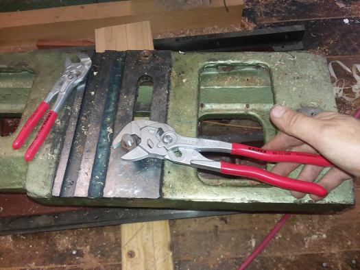
Here’s a picture showing, from top to bottom, the Wadkin handle, below that the Robinson handle, and below, their replacements, nice cast zinc Kipp ‘classic’ handles:

While some have said on a particular forum that late model Wadkin machines had very fine casting quality. I would beg to differ. The reason I had the sides of the support beam machined clean was their blobby poor castings. While pits and voids are not all that unusual in sand castings, it is unfortunate to find such craters as these right on a cast surface where the guide bar mounts:

Fortunately, in the above case it doesn’t really affect anything to have those pits there, but still.
Prior to fitting the sliding table, I decided to level up my main table. A little overkill perhaps, to use the Starrett Master Precision level for such a task, but I tend to prefer to reduce uncertainties where I can:

Once the machine frame and thereby the main table was leveled, I could take a look at how the angle brackets sit, relative to that. Note that the set screws which are used to adjust the angle brackets have never been touched since I removed the brackets, and the position they gave the angle brackets is that which was also factory pinned:

The main table, by the way, is simply a large casting resting directly upon the cast frames four mounting points – it is not shimmed or anything like that so the relationship between the main table and the frame should be much the same as it was when the machine left the factory, save for any movement which might have unfolded in the machine base casting over time. I was somewhat surprised to find it was not especially well aligned to the main table.
The other angle bracket is similarly out of plane with the main table:

So, I set to work bringing the brackets up roughly 1/16″ (1.6mm) and leveling them to the same plane as the main table:

With that taken care of, the angle brackets were bolted a little more tightly, and the support table put on:

The support table slides inward, guided by a square bar on one end, until it bumps into a pair of stops:

I have the stop bolt on the wrong part in this picture – the adjusting bolt is supposed to mount on the dark metal boss on the side of the support table casting. That was put right a little later on. You can also see in the above picture that the linear bearing rods, packing pieces, securing bar, and end caps have been fitted.
Next it was time to deal with the linear rail assemblies for the upper sliding table. These consist of paired sets of 3″ long linear rods contained in a channel, with a 1/4″ x 1/8″ steel packing piece in between to lock them in place. One of these packing pieces evidenced damage from ball bearings running along its edge, an indicator that the packing was not fully seated:

So, I drove that packing piece down, and then discovered another section which needed the same attention. Once those were sorted, I bolted them to the underside of the sliding table, but did not tighten the bolts all the way down quite yet.
Then came time to put the sliding table in place and fit the bearings. This looked simple enough but it proved to be a bit vexing.
The ball bearings which run between the linear rails are kept together, and spaced from one another by way of a plastic strip with holes every 1″ in space for a bearing. There is a plastic strip on each side, and the two plastic strips are kept running in unison by a sheet metal plate which looks a bit like the letter ‘M’ on end.
The first fitting of the ball bearings took me about 45 minutes. They have to be fed in one by one. I got them in and the table slid smoothly but came to a sudden metal-on-metal stop before the table could extend fully out on the infeed side. Hmm. That’s how day 1 ended, with me scratching my head and feeling decidedly non-chuffed.
Day 2 began with removing the metal retainer plate, the plastic bearing cages, and all the individual ball bearings. After reinserting the parts, I could move the table but something was binding. Out came the retainer and cages and balls once again. It turned out that one of the plastic cages was misaligned with the retainer.
Third time fitting I made some slight mods to the plastic cages and got everything in okay, but when the table was slid it felt like the metal retainer plate was dragging on something internally. There was no way to see inside, so back apart it had to come again. I looked at the retainer plate and saw the wear pattern on its underside, which had clearly happened before, and then found the culprit: a raised numeral ‘1’ on the cast-in part number on the surface of the support beam was rubbed clean of paint. I’d noticed it when i put the support beam into place initially, but didn’t think much about it. I got out the angle grinder and decked that down.
The 4th time was the charm. The sliding table worked just right, and I adjusted the slop out with the provided adjustment screws along the edge of the sliding table.
At long last the sliding table was rolling smoothly:

A look at the mitre fence, all geometrically sorted, flat and straight, and with brand new pivot bolt:

A straightedge was used to gauge roughly the height that the sliding table needed to be at:

Then I used the Master Precision level to get it dead level with the main table. After all that I can say it was, based on what I have seen, better than factory perhaps, and if not, by no means worse.
With the sliding table in position, the next step was to check how it was aligned with the saw blade, as the table needs to run dead parallel with the blade to obtain dead-on 90˚ cuts. The thing to keep in mind with the sliding table is that it is guided laterally by a square metal bar, and thus the table itself cannot be toed in or toed out relative to the saw blade. The sliding table runs therefore in one possible alignment only relative to the main table and saw blade.
As with things before the sliding table rebuild, the saw blade proved to be out of alignment with the sliding table. In the past I had simply pushed the far end of the sliding table over a bit and locked it down, slightly torquing again the aforementioned metal guide bar. However that was an unreliable solution, since every time one pulled the table back to change a blade and then pushed the table back into place it would be easy to not quite push it far enough over into position. It was an invitation to bringing slight errors in to the mix. And I didn’t like torquing a part into misalignment with it’s mechanism – I’d rather get things aligned as they should be.
This time, I was not going to put up with that, and since Rees had done a little work to tighten up the fit of the guide bar to the sliding table I was not going to be doing any more pushing of the table to force it into slight misalignment to that guide bar. The adjustment of the saw blade relative to the travel of the sliding table had to be accomplished another way.
That ‘other way’ had been clear to me from the last time I had gone through the process of aligning the saw a couple of years back: the saw trunnion had to be aligned to the sliding table.
What kept me from doing that previously was a feeling that the factory positioning of the trunnion was a sacrosanct thing. You see, when the machine was aligned at the factory, they drove pins into the connections after they were bolted. I hesitated to touch those pins because surely the factory put it all together, presumably perfectly(?). Who am I to dare mess with that?
Well, one thing changed my mind, and that was the situation with the two angle brackets which attach to the sides of the cast machine frame, and which carry the sliding table’s lower support beam. I removed them during the tear down of the sliding table, so they could be checked out by Rees. Upon inspection, they turned out to be very accurately at 90˚ and nice and flat on both surfaces. But with the table itself being decked down to get it flat I knew that the compensation for the loss of height would have to be taken up by raising those angled support blocks.
The curious thing about those blocks was the way in which they are mounted onto the frame of the machine: they are bolted and pinned, AND there are a pair of set-screws beneath each of them for the purposes of adjusting the height.
And if you read the factory manual for the saw, they mention that if the height of the sliding table needs to be brought up, then one should drive the pins out, loosen the bolts, and adjust the height via the two set screws.
Of course, once one has made any adjustment to the angle block’s height via those set screws, the locating pins can no longer be used. In fact, it strikes me as a bit of an odd design to make a part which is intended from the get-go to be capable of being adjusted, and then to drive locating pins into it as well. Rees also thought it was an odd thing, and he is a machine designer mainly.
So, reflecting upon this I quickly got over any lingering trepidation I was having in regards to removing the locating pins. The saw trunnion was out of whack relative to the sliding table, and had to be moved. Just because the factory had set the location with locating pins didn’t matter.
Now, one can ponder how it is that the factory setting for the trunnion is out of alignment with the sliding table – and not by a little I will add – whether it left the factory in less than perfect alignment or whether the machine frame casting has moved sufficiently, say, to cause the misalignment. At the end of the day, speculation as to cause is moot- the pins needed to be removed so alignment could be attained.
Once I got to that determination, I got to work. Well, there was a slight snag which tended to lead me to hum and haw a bit, and that was the inconvenient fact that while the trunnion locating pins are one side of the saw were easy to access, the ones to the other side could only be accessed by removing the main table. My machine has the fairly rare extra long table, with about 72″ (1.83m) of rip capacity, and is comprised of two tables (three actually, counting the outboard support piece where the fence can be parked), so I had to deal with that complication.
Here we at last have the main table off to one side, after previously separating the outboard table:

It’s been a while since I peered into the innards of this machine:

Once the pins were out of the trunnion mounting brackets, and the bolts slackened off, I was able to move the trunnion into alignment. After a bit of fiddling, I was able to attain an alignment of +/- 0.0001″ along the surface of a 16″ diameter blade.
Here’s the right side (outfeed), indicator at 0:

At the middle of the saw plate one can see that the reading is some 0.0046″ less, due to the saw plate being slightly hollow ground:

And then we get to the other side, to the same relative point at the outside of the saw blade, indicator again at 0:

I feel that accurate aligning to 0.0001″ is going to work for me. At last the friggin’ trunnion is aligned! Damn that has been bugging me for a long time. So nice to sort it out. Locating pins schmocating pins…
With the trunnion where it needed to be, the next task was to put the main table back on. Then, before the bolts for that were tightened, I measured with a caliper at both ends of the table and adjusted the main table until it was parallel with the sliding table.
At the outboard end:

At the inboard end:

Satisfied with that, I cinched the table mounting bolts down and reconnected the outboard table.
The last task was to re-align the rip fence. It should run more or less parallel to the saw blade, and then open away from the saw blade slightly as you exit the cut. The factory manual calls for the fence to open 0.004″ away. Seemed reasonable.
Checking the rip fence with an indicator seemed logical enough, as the fence had to more or less run parallel to the sliding table, until we were on the exit portion from the blade. I had looked at this casting with a straightedge previously, and today as well, and it seemed pretty flat, but the indicator revealed that it was in fact slightly bowed.
So, at some point I’ll be taking that fence casting to Rees and get him to machine it flat. For the time being I adjusted it as best I could, making sure it opened an adequate amount at the outfeed side.
At the infeed end of the fence, we start with the indicator on 0.0027″:

At the middle of the fence the number has decreased, due to the hollow, some 0.0035″ or so:

Yah, its a relatively small amount, but when you look at things with a 0.0001″ graduated indicator, small amounts can look enormous. Still, the information is useful.
At the outfeed side, we had returned slightly, but not quite back to where we started, so the fence is opening away from the blade a small amount – probably too small an amount really:

I may well have to increase that amount in the near future- a test cut or three will determine how it is cutting along the rip fence.
For now I am satisfied -no, delighted – that after nearly two full days of work, this saw is ready for action once again, at last with a flat sliding table, and good alignment between sliding table, trunnion, main table and rip fence. A last step was to fit a new mahogany infill strip around the blade and raise the blade up into it:

One of the reasons I like the Wadkin saw, in terms of its ‘bones’ is that it is one of the few saws of this type which can handle an 18″ blade and fully retract the blade below the table. Currently a 16″ saw blade is fitted, and as you can see in the above picture it gives a decent amount of cutting height.
A look at the infeed end – I kinda like the clean bare cast iron look along the edge, where once there was lumpy painted cast iron with scabby paint:

At some later point, I will paint the machine, but probably not those edges. Well, I’ll figure that out when I get there I guess.
A look along the long side of the sliding table assembly, with one of those new Kipp handles in view:

The planed table surface looks great- and did I mention it is dead flat?:

I gave the table a coat of Boeshield after cleaning it with lacquer thinner several times:

Thus concludes Phase I of the saw rebuild. Not sure when ‘Phase II’ will get underway, but it will be a few months off I would imagine. The next post in this series concerns work on the protractor casting.
I guess it is time to get back to some woodwork. Thanks for visiting the Carpentry Way.
Hi Chris
Great blog post.
I once read a book on performance tuning of two stroke motorcycles, and the author wrote that he sometimes suspected factories to bolt things up just to make it easier to ship. That could be the case of the Wadkin as well.
If the saw was shipped with a pinned trunnion in a position that would allow the machine to be used, they would most likely never hear from any future owners of that saw. Few people would take the time and effort to do what you have done.
But I think the effort is well worth it. There is something about a really stable piece of machinery that will give dead accurate results when it is used.
I don’t think that I would have the courage to alter the position of something that was pinned, but luckily I have never had to. So far the only think that I can think of in my possession with a pinned part is my old MAS SN20 metal lathe which has got the removable bridge part pinned, for accurate relocation.
I actually ought to fix a small problem in the gearbox, but I never seem to be able to find the time to do that.
Brgds
Jonas
Jonas,
great to hear from you!
Wadkin has a reputation among its fanciers, whom some call ‘Waddies’, for being made by ‘proper engineers’ in white coats and meticulously built. I guess that might have been the case with machines of a certain era, but by the late 1960’s it would appear that quality was becoming less consistent.
I’ve found enough things on my machine that indicate that either the original factory setting given by the pin placements were off the mark, or castings moved over time, which does shed a dubious light on the quality of the casting process. It should be noted that at least the machines CAN be adjusted, once you surrender attachment to the pins, something that can not be said for a great number of woodworking machines out there, particularly is made in the last 30 years.
Besides the alignment and casting quality issues, there are some odd design aspects that I think should have been apparent over time and the saw should have seen those things improved, but they were not. It seems like a combination of changing market winds, and perhaps complacency or financial strains that conspired to make refinements to these saws an opportunity missed.
Again, I think it has ‘good bones’, can be adjusted or rebuilt to obtain good geometry, and I’m hoping, after repairs and improvements have been made, it will be a keeper for me. Other, more modern saws, do tempt of course….
GLORIOUS! Congratulations. Better than new, for sure!
Oh, thanks Jamie! I’m trying to do right by the machine, and simply want it to be able to do the things saws are meant to do, accurately and repeatably.
I’ve noticed the factory settings in some cases are just not that accurate. One tends to assume that in a place where the item was designed and someone presumably builds them daily, the checking methods would be really top notch. Most often they are pretty good, but sometimes it seems they’re just not good enough for accurate work.
Anything done at the factory would have been a balance between accuracy and cost.
I do not think that the adjustment at the factory was done like Chris has done it. That would probably have been way to time consuming and expensive.
As a production engineer myself I would have made a tool that clamped around the trunnion and referenced on the guides of the sliding table. That would allow reasonably accurate adjustment in a short amount of time. OTOH, maybe they just used a square and eyeballed it. 🙂
Same goes for the castings. Sure, it would be nicer not to have cavities. But unless they’re in a crucial spot some would have been allowed.
Roland,
I think youŕe right that the factory would not have gone about machine alignment the same way I did, but would have relied upon setting jigs. I have no idea how much time they might have spent on that phase of the machine build, nor do I have any idea what standard of accuracy for which they were aiming.
You are also correct about the castings being accepted even if imperfect, but the castings on my machine, especially the support beam for the sliding table, are worse it would appear than several other Wadkin PP saws I have seen.
Brian,
I´m not really sure what to make of the misalignment that was present in several of the factory pinned settings.
Either the alignment wasn´t so great coming out of the factory, or the casting distorted via long-term movement, or some combination of both. In any case, the good thing was that the parts to be adjusted to obtain good alignment, which is more than can be said for some other machines.
Although I haven’t been able to find anything w.r.t. accuracy in the old Wadkin documentation, it would not surprise me if this machine is now *better* than when it was new. The sliding table looks fantastic.
As for the pins in the brackets, I can see at least two possible reasons. This could be a “quick fix” for a design flaw. Maybe the mounting backets could vibrate loose after a while or in certain conditions. Pinning it after assembly was probably easier than doing a redesign and change the production tooling.
Or it could be that the obtainable tolerances of the parts exceeded the required tolerance of the assembly. In that case, adjusting the fit and pinning the parts could be seen as an acceptable solution. Especially for a part that presumably should last the lifetime of the machine. I have seen this trick being used before.
Nice work Chris. Making it work like a saw should.
Mark,
appreciate the compliment, coming from a fellow who rebuilds machines for a living. Thanks also for the subscribe!